

Fleet telematics hardware connection: 2026 guide
Getting your fleet telematics hardware connection right from the outset is the difference between a system that actively protects your business and one that quietly fails you. Poor installation leads to data gaps, missed compliance windows, and drivers who appear off the radar when they shouldn’t be. Whether you’re adding GPS fleet telematics to a single van or rolling out telematics device integration across a mixed HGV fleet, the physical and electronic connection quality underpins everything. This guide covers prerequisites, step-by-step installation, troubleshooting, and post-install verification, so you can deploy with confidence.
Table of Contents
- Key takeaways
- What you need before connecting telematics hardware
- Step-by-step: connecting telematics hardware to vehicles
- Troubleshooting common hardware connection problems
- Verifying connectivity and confirming system activation
- My perspective on getting hardware connection right
- How Fleetalyse supports your telematics setup
- FAQ
Key takeaways
| Point | Details |
|---|---|
| Preparation prevents failure | Gather tools, understand vehicle electrical systems, and plan per vehicle type before touching any hardware. |
| Match method to device type | Plug-and-play OBD-II suits quick deployment; hardwired installations require more time but deliver greater reliability. |
| Physical faults dominate failures | Over 60% of ELD compliance failures trace back to hardware faults, not software, making cable quality critical. |
| Verify before you close up | Always confirm GPS lock, live data flow, and device-specific functions before reassembling trim panels. |
| Open platforms protect your investment | Choosing telematics partners with open APIs prevents vendor lock-in and supports long-term fleet scalability. |
What you need before connecting telematics hardware
Before a single cable is touched, preparation separates a clean installation from an afternoon of diagnostic headaches. Fleet management connectivity starts with knowing exactly what hardware you are deploying and what each vehicle type demands.
Common hardware types in fleet telematics
The most frequently deployed devices across UK commercial fleets include:
- GPS trackers (hardwired or OBD-II): Provide continuous vehicle location data and form the backbone of any GPS fleet telematics setup.
- OBD-II plug-in units: Suited to vans and lighter vehicles with accessible diagnostic ports; no tools required.
- Dashcams: Forward and dual-facing cameras that require a reliable, permanent power source and careful mounting to avoid airbag zones.
- Electronic Logging Devices (ELDs): Connect to the vehicle’s J1939 network via a 9-pin connector and log driver hours for compliance purposes.
- Tachograph head units: Standard on UK HGVs, these integrate directly with the vehicle’s data network and require specialist connection harnesses.
Tools and materials required
| Tool or material | Purpose |
|---|---|
| Multimeter | Testing voltage, continuity, and ground quality |
| CAN sniffer / diagnostic tool | Isolating J1939/CAN bus communication faults |
| Wiring loom and cable ties | Routing and securing cables neatly behind trim |
| Panel removal tools | Accessing trim without damage |
| Fuse taps and add-a-fuse kits | Safe power tapping from fuse blocks |
| Mounting brackets and adhesive pads | Securing devices in approved positions |
| Heat shrink tubing | Weatherproofing and insulating connections |
Vehicle preparation matters as much as the tools themselves. Disconnect the battery or isolate the relevant circuit before working on any wiring. Telematics devices require a clear sky view for GPS modules, safe mounting locations that avoid airbag deployment zones for dashcams, and accessible positioning for ELD tablets. Ignoring these placement rules risks both device performance and vehicle safety compliance.
Pro Tip: Before starting any installation, photograph the existing wiring loom and fuse block layout. If something goes wrong during the job, you have an accurate reference point to revert to.
Understanding the vehicle’s electrical architecture is non-negotiable for hardwired installs. On HGVs, the 24V system behaves differently from the 12V systems in vans and light commercials. Verify supply voltage, identify the ignition-switched circuit (so the device activates only when the engine is running), and locate a solid chassis ground point before committing to any permanent connections.
Step-by-step: connecting telematics hardware to vehicles
The physical connection process divides cleanly into two categories depending on device type. Choosing the right approach for each device saves time and avoids unnecessary rework.
OBD-II plug-and-play vs hardwired installations
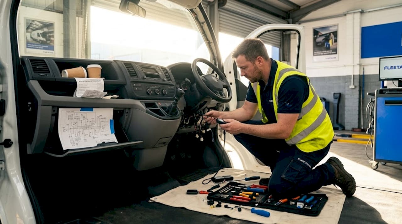
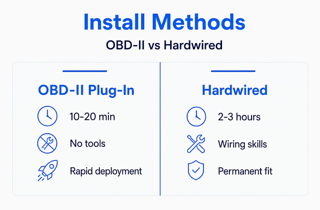
Plug-and-play OBD-II devices install within 10 to 20 minutes and require no tools, making them practical for rapid deployment on vans and cars. Hardwired GPS trackers, dashcams, and ELDs typically require 45 to 90 minutes of professional labour per device, and multi-device installations often take 2 to 3 hours per vehicle when wiring GPS trackers, cameras, and ELDs together correctly.
| Installation type | Typical time | Tools required | Best suited for |
|---|---|---|---|
| OBD-II plug-in | 10–20 minutes | None | Vans, cars, light commercial |
| Hardwired GPS tracker | 45–90 minutes | Full toolkit | HGVs, trailers, assets |
| Multi-device (GPS + cam + ELD) | 2–3 hours | Full toolkit | HGVs, compliance-critical vehicles |
Hardwired installation: the process
Follow these steps for a reliable hardwired fleet telematics hardware connection:
- Isolate the vehicle circuit. Disconnect the battery negative terminal or use a circuit isolator. Never work on live wiring.
- Remove relevant trim panels. Use plastic panel removal tools to avoid scratching or cracking interior trim. Work methodically from one edge.
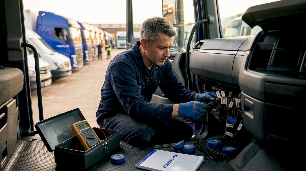
- Identify power, ground, and ignition circuits. Use your multimeter to confirm a constant 12V or 24V supply, a clean chassis ground (resistance under 0.1 ohms is the target), and an ignition-switched feed that drops to zero with the engine off.
- Route cables behind trim. Feed wiring through existing grommets where possible. Avoid routing near heat sources, sharp edges, or moving components. Use cable ties every 15 to 20 centimetres to secure the loom.
- Connect to the fuse block. Use add-a-fuse taps on appropriately rated circuits. Never exceed the existing fuse rating or splice directly into a critical vehicle circuit.
- Terminate connections cleanly. Crimped connectors with heat shrink provide a far more reliable joint than twisted and taped wires, particularly in the vibration-heavy environment of an HGV cab.
- Connect to the J1939/CAN bus where required. For ELDs and tachograph-linked devices, connect via the vehicle’s 9-pin J1939 diagnostic connector or purpose-made connection harness. Confirm the correct pin assignments for your specific vehicle make and model.
- Mount the device securely. GPS antennas need a clear sky view through the windscreen or roof. Dashcams must sit within the wiper’s swept area and away from airbag zones.
- Reconnect the battery and power up. Observe the device’s LED indicators or diagnostic screen to confirm it has powered on correctly.
Pro Tip: When connecting multiple devices, label every cable before routing it. On a vehicle with GPS tracker, dual dashcam, and ELD all installed simultaneously, an unlabelled loom becomes a serious problem the moment you need to diagnose a fault six months later.
For vehicles fitted with analogue tachographs or digital tachograph head units, telematics device integration requires a compatible harness that draws data from the tachograph’s C connector or K-line interface. This is where Fleetalyse’s pre-configured connection harnesses make a genuine difference, removing the guesswork from vehicle-specific wiring assignments.
Troubleshooting common hardware connection problems
Even well-planned installations encounter faults. Knowing where to look first saves hours of wasted diagnostic time.
The most common physical failure points are:
- Loose or corroded ground connections: The single most frequent cause of intermittent GPS dropouts and power cycling. A ground point that tests correctly on day one can oxidise within weeks in a humid cab environment.
- Cable fatigue at flex points: Wiring routed through door hinges or over sharp trim edges will eventually develop micro-fractures. These are invisible to the eye but show up immediately with a continuity test.
- Poorly seated connectors: Particularly on J1939 9-pin connectors, a connector that feels clicked in may not be fully seated. A half-seated J1939 connection passes visual inspection but intermittently drops the data link under vibration.
- Incorrect fuse rating: An undersized fuse will blow repeatedly; an oversized fuse may fail to protect the device’s internal circuitry.
Over 60% of ELD compliance audit failures trace to physical hardware faults, particularly J1939 data cable failures, rather than software problems. The implication is clear: when an ELD throws a compliance error, start at the cable, not the configuration menu.
For CAN bus and J1939 network issues, physical layer faults including power, ground, and termination cause approximately 70% of “no data” problems. A basic CAN sniffer can isolate these faults within minutes. If the sniffer sees no traffic at all, the fault is almost certainly physical. If it sees malformed frames, you may have a termination or address conflict issue between devices.
High-quality J1939 cables with correct shielding and termination prevent over 60% of compliance audit failures. Visual checks are insufficient; lab tests reveal load-cycling faults that are invisible to the naked eye.
Multi-device setups introduce address conflict risks. When a GPS tracker, ELD, and tachograph download module all share the same J1939 bus, each must operate on a unique address. Conflicts cause one or more devices to drop off the network silently. Check the device manufacturer’s documentation to confirm configurable address settings and adjust where necessary.
Electromagnetic interference (EMI) is an underappreciated problem, particularly in HGVs with inverters, refrigeration units, or strobe lighting. Route data cables away from high-current power cables wherever possible, and use shielded cable for CAN bus connections. Choosing telematics partners with open platforms and documented SDKs also simplifies troubleshooting when the fault lies at the software configuration level rather than the physical layer.
Pro Tip: If a device repeatedly loses connection after rain or a vehicle wash, suspect a ground point that is wicking moisture. Clean the ground location, apply an anti-corrosion compound, and recheck with a multimeter before reassembling.
Knowing when to call for professional support matters too. If you have exhausted physical checks and the fault persists across multiple devices, the issue may lie within the vehicle’s own ECU or data network. At that point, a diagnostic technician with OEM-level tooling is the right call.
Verifying connectivity and confirming system activation
The installation is not complete until the data is flowing correctly. Post-install verification is the step that prevents you from discovering a fault three weeks later when you are already in an audit.
A stable telematics installation requires verification of GPS lock, cellular signal strength, live data flow into the fleet management platform, and device-specific functions after completing hardware setup.
| Verification check | What to confirm | How to test |
|---|---|---|
| GPS lock | Device acquires satellite fix within 90 seconds outdoors | Check LED indicator or platform map view |
| Cellular connectivity | SIM registers on network; data transmits | Platform shows live vehicle position |
| Live data flow | Platform receives speed, ignition state, mileage | Review live vehicle activity feed |
| Dashcam upload | Video clips upload on trigger or schedule | Check platform media library |
| ELD / tachograph logging | Driver hours record correctly | Review driver activity report |
| CAN bus data | Fuel consumption, RPM, fault codes populate | Confirm in platform analytics dashboard |
Work through each check systematically before reassembling trim panels and closing out the job. The practical steps are:
- Move the vehicle outdoors or to a clear area and wait for GPS lock confirmation on the platform.
- Verify the vehicle appears as a live dot on your fleet management platform, with accurate position updating every 30 to 60 seconds.
- Start and stop the engine to confirm ignition-on and ignition-off events are logged correctly.
- Trigger a dashcam event manually (most devices have a test button) and confirm the clip appears in the platform media library.
- For ELD or tachograph-connected devices, log a short driver activity session and verify hours record against the expected output.
Ongoing maintenance schedules should include a quarterly check of ground connection quality and cable condition, particularly on vehicles operating in demanding environments such as tipper trucks, refrigerated units, or vehicles frequently exposed to power washing.
My perspective on getting hardware connection right
I’ve seen more compliance failures that trace back to a single loose ground wire than I care to count. The frustrating part is that most of them were entirely preventable.
In my experience, the hardest thing to shift in fleet operations is the assumption that connecting telematics hardware is a quick job. Operators will spend serious money on a premium GPS fleet telematics platform and then try to cut corners on the physical installation. That logic works in reverse. A poorly connected device feeding inaccurate data or dropping off the network entirely will undermine the value of even the best fleet management connectivity platform you can buy.
What I have learned from working with mixed fleets, particularly those running HGVs alongside vans and trailers, is that the variation in vehicle types is where most installation programmes fall apart. A process that works on a Euro 6 curtainsider will not automatically translate to an older tractor unit with a different J1939 pinout. Documenting the specific wiring configuration for each vehicle make and model, and keeping that record updated, is the kind of unglamorous work that pays dividends during audits and fault-finding.
The advice I keep returning to on vendor selection is this: open API platforms that give you documented integration routes are worth far more than closed ecosystems with impressive feature lists. As UK courier and logistics technology evolves, the operators who invested in open, scalable hardware connections are the ones with the flexibility to adapt. The ones locked into proprietary hardware are the ones renegotiating expensive contracts.
Invest in the physical installation properly at the outset. The cost of rework, a missed DVSA inspection, or a contested insurance claim will always exceed what it would have cost to do it correctly the first time.
— Vytautas
How Fleetalyse supports your telematics setup
If the installation process described in this guide feels like a significant undertaking for your fleet, you do not have to approach it alone. Fleetalyse provides a full range of GPS trackers, dashcams, and accessories designed specifically for UK commercial fleets, including plug-and-play units and purpose-built connection harnesses for HGVs and vans.
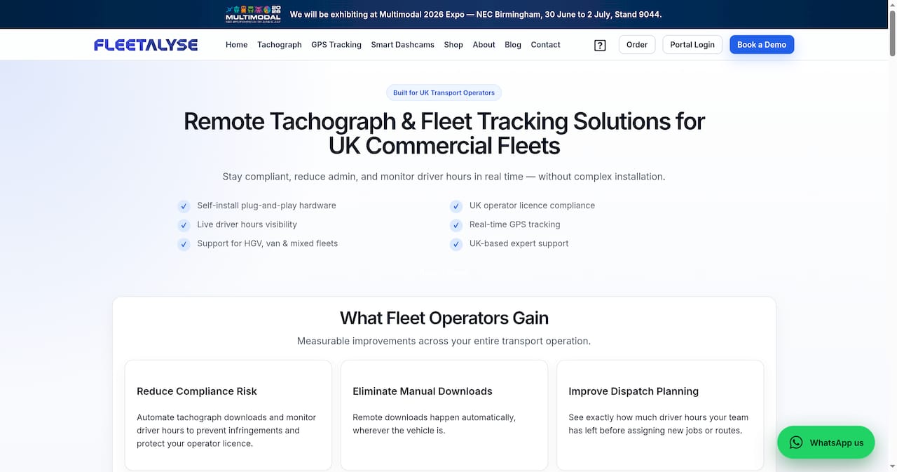
Beyond hardware, the Fleetalyse platform integrates GPS vehicle tracking, driver behaviour monitoring, remote tachograph downloads, and compliance reporting into a single dashboard. UK-based support means that when you have an installation question or a connectivity fault to diagnose, you speak to someone who understands DVSA regulations and Operator Licence requirements, not a generic helpdesk. Whether you are connecting your first telematics device or rolling out hardware across a fleet of 200 vehicles, Fleetalyse is built to support every stage of that process.
FAQ
What is the fastest way to connect a telematics device to a vehicle?
Plug-and-play OBD-II devices are the quickest option, installing in 10 to 20 minutes with no tools required. They are best suited to vans and light commercial vehicles with an accessible OBD-II port.
Why does my ELD keep losing its data connection?
J1939 data cable failures are the leading cause of ELD compliance failures, accounting for over 60% of audit issues. Check cable seating, shielding quality, and connector condition before investigating software settings.
How long does a full multi-device telematics installation take?
Fitting a GPS tracker, dashcam, and ELD on a single HGV typically takes 2 to 3 hours when all devices are wired correctly. Rushing this process is the primary cause of intermittent faults.
How do I know my telematics hardware is connected and working correctly?
After installation, confirm GPS lock outdoors, verify the vehicle appears live on your fleet management platform, and check that ignition events, driver hours, and any dashcam uploads are recording as expected.
What causes “no data” errors on a J1939 or CAN bus telematics system?
Physical layer faults including power, ground, and termination issues account for around 70% of CAN bus “no data” problems. Use a CAN sniffer to confirm whether the network is active before investigating device configuration.